Abstract
Over time the harsh outdoor environment wears away at asphalt surfaces. Asphalt emulsion is sprayed onto the surface to act as a sacrificial barrier. To pump this asphalt emulsion for spray application an effective pressure relief device must be incorporated. High pressure is needed to achieve the desired spray pattern, but this same pressure can cause components to fail in the presence of a pressure spike. Hydraulically driven positive displacement pumps are used to pump the emulsion, so a pinched hoses or a clog in the system results in a severe pressure spike. Due to the emulsions viscosity and abrasive additives a direct relief device is not suitable for long term service. A remote activated pressure relief device is needed to allow adequate spray pressure and prevent system failure. The device is manufactured with off the shelf hydraulic and pneumatic parts bolted to a steel base plate. A pilot pressure is taken from the emulsion circuit and feeds a pneumatic cylinder that pulls a linearly actuated hydraulic valve, in turn diverting the hydraulic flow to the reservoir instead of driving the pump. The pull of the cylinder is balanced by an adjustable spring to allow for different pressure settings. After installing the pressure relief device pressure was be measured at different locations throughout the system. The emulsion pressure relief device performed an as engineered and the pressure remained between 50 and 90 psi.
Introduction
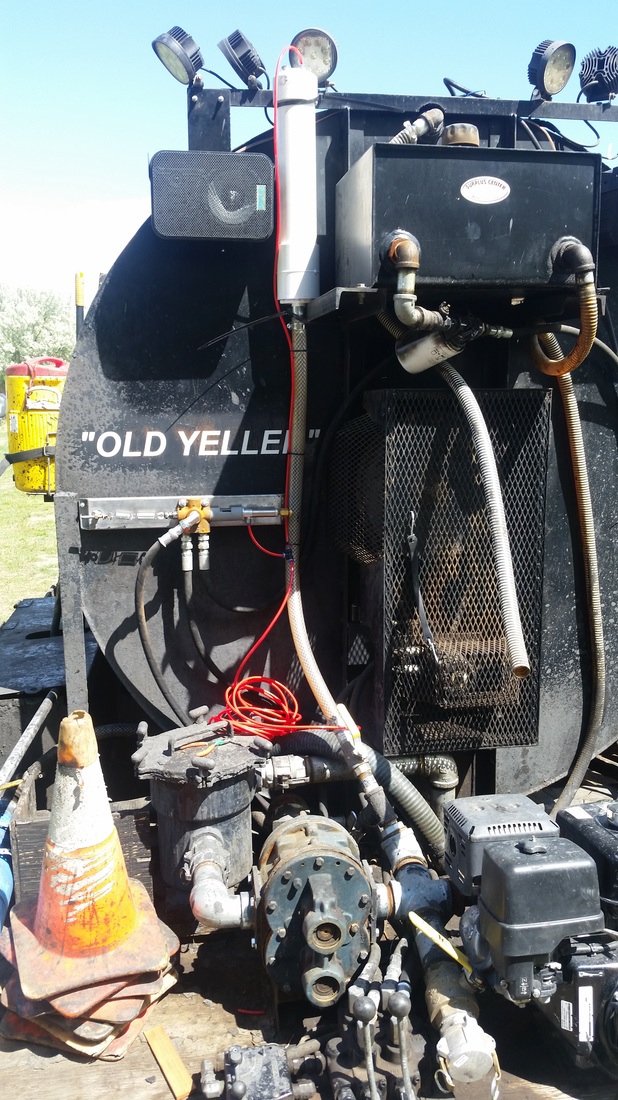
This project stems from the need for an effective pressure relief system bridging two fluid circuits. One circuit is an asphalt emulsion pump system, and the other is the hydraulic power system. One of the thing my job requires is to build and maintain equipment. The company is Central Sealcoat, and the device I’m building will be for the emulsion pump on a truck. In its original design the pump requires 2 people to operate, 1 controlling the pump and 1 operating the dispensing hose. With an effective pressure relief system the pump could be turned on and operated by a single person. The emulsion consists of asphalt, emulsified with water by use of detergents. Sand, clay, and fiber are then added to the emulsion to add strength once dried. The emulsion is a difficult material to pump as it varies in viscosity dependent on water concentration, the sand additive is abrasive, and solids settle out of suspension causing clogs. The pump used to pump the emulsion is a Bowie brand, positive displacement gear pump driven by a hydraulic motor. Due to the nature of the emulsion material a direct pressure relief device is not commercially available or practical. In its original design the pump system requires 2 people to operate, one controlling the hydraulic motor driving the pump and one operating the dispensing hose. With a pressure relief system the pump could actuated, and operated safely and efficiently by a single person.
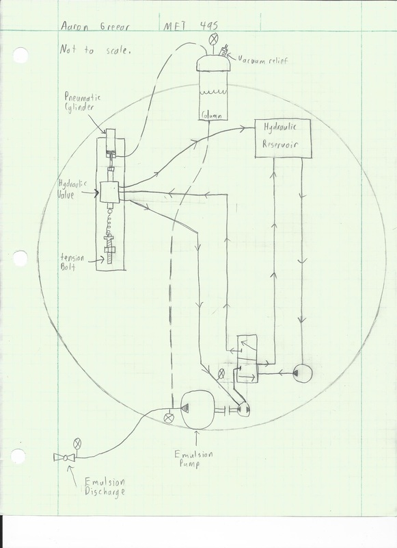
Since the emulsion and air are in direct contact, the air pressure delivered to the cylinder will directly reflect the pressure in the emulsion system. This pressure will be fed to a pneumatic cylinder that pulls a linearly actuated hydraulic valve, in turn diverting the hydraulic flow to the reservoir instead of driving the pump. Because of the difficulty involved in finding the perfectly matched pneumatic cylinder for the desired pressure, an adjustment spring will be used to resist the cylinder (schematic 1 Appendix B). The spring will be tensioned using the threads of a bolt to move it linearly through a stationary nut.
Since the emulsion and air are in direct contact, the air pressure delivered to the cylinder will directly reflect the pressure in the emulsion system. This pressure will be fed to a pneumatic cylinder that pulls a linearly actuated hydraulic valve, in turn diverting the hydraulic flow to the reservoir instead of driving the pump. Because of the difficulty involved in finding the perfectly matched pneumatic cylinder for the desired pressure, an adjustment spring will be used to resist the cylinder (schematic 1 Appendix B). The spring will be tensioned using the threads of a bolt to move it linearly through a stationary nut.
Design
The pilot pressure signal could be transmitted through fluid, air, or electronically. Through fluid would be the easiest, electronically would be the simplest, but pneumatically seems to pose the least overwhelming design obstacles. Most fluids would be soluble with the emulsion because the emulsion consists of both water and oil. A piston apparatus could be used to separate the two fluids but the sand would wear at the seals and bore over time. An electronic system would not be compatible with the existing hydraulic components, resulting in a costly system remake, taking more time and resources. By using air as the media of transfer there will be no contamination with the emulsion. A simple column will be used to keep the two media separated. Gravity will keep the fluid at the bottom, and because it’s a closed system, it will hold pressure and stop the emulsion from filling the column. Using a pneumatic system has a unique advantage as a surge control device. The added air will compress with raising pressures, buffering the pump surges.
Analysis
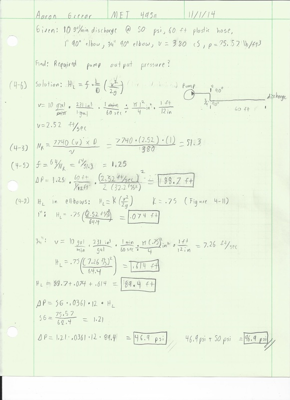
The required pressure of 50 psi for the emulsion pump is measured at the end of the discharge hose. This pressure is required when the fluid is flowing, so there is a pressure drop between the pump and the end of the discharge hose that must be accounted for. The pressure drop attributed to fluid friction will be approximately 46 psi (Appendix A, 4). The pressure drop is considered approximate because is based on the manufacturer spec for the fluid viscosity which can change with water concentration [4]. The pressure drop from 60 feet of hose and two 90º bends is added to 50 psi to get 96 psi required at the pump output. This value is used to determine the amount of spring tension resisting the pneumatic cylinder. The static pressure of 3.15 psi from the emulsion in the tank will be used as well (Appendix A, 2). The fluid column will be located at the top of the tank so the static pressure will be counteracting the pilot pressure whenever the tank is anything but full. In order to maintain a minimum of 50 psi at the discharge hose there must be 99.15 psi at the emulsion pump output.
In order to keep the emulsion from ever getting into the air system the max compression of the gas in the system must be found. If the emulsion tank is full, the air column must have a certain volume above the emulsion tank so that it will not completely fill with emulsion once the system is pressurized. The volume above the emulsion tank must be proportional to the volume of air occupying the pneumatic lines plus the volume inside the pneumatic cylinder. The volume required with a safety factor of 2 is 53.8 in3. This equates to a 17.1” tall 2” diameter column, or a 7.6” tall 3” diameter column (Appendix A, 5). Due to the existing height of the truck and emulsion tank a 3” column diameter will be used to keep overall truck height to a minimum. The 7.6” is height above the emulsion tank required. An overall length of 16” will be used so it can be secured on the part below the top of the tank.
In order to keep the emulsion from ever getting into the air system the max compression of the gas in the system must be found. If the emulsion tank is full, the air column must have a certain volume above the emulsion tank so that it will not completely fill with emulsion once the system is pressurized. The volume above the emulsion tank must be proportional to the volume of air occupying the pneumatic lines plus the volume inside the pneumatic cylinder. The volume required with a safety factor of 2 is 53.8 in3. This equates to a 17.1” tall 2” diameter column, or a 7.6” tall 3” diameter column (Appendix A, 5). Due to the existing height of the truck and emulsion tank a 3” column diameter will be used to keep overall truck height to a minimum. The 7.6” is height above the emulsion tank required. An overall length of 16” will be used so it can be secured on the part below the top of the tank.
Construction
Pressure column construction
· 3” Schedule 40 PVC pipe will be used due to its high pressure rating and thick walls that allow it to be easily drilled and tapped for pipe thread. Cast Iron could be used, but would be more expensive and harder to drill/tap. Copper is another possibility, but would be even more expensive and would require soldering threaded bungs in place. Schedule 40 PVC is rated at 240 psi and the system should never reach a pressure higher than 150.
· The column will have a 1” NPT port on the bottom that will plumed to the output of the emulsion pump using PVC flex line and barb fittings. There is already a 1” line on the emulsion tank that can be directly connected to the column.
· On the top of the column there will be a cap has 2 holes drilled and tapped to 1/4“ NPT. One will have a vacuum relief valve and the other a push fitting for the pneumatic pilot pressure.
· The column will be mounted at the top of the emulsion tank using zip ties to secure it to existing structure.
Adapting hydraulic valve
· One end of shaft will get a ¼-28 nut welded on it to accommodate the threads on the pneumatic cylinder shaft
· Opposing end of shaft will have a 3/8-16 nut welded on where an I-bolt will be inserted for connecting the tension spring.
Valve Bracket construction
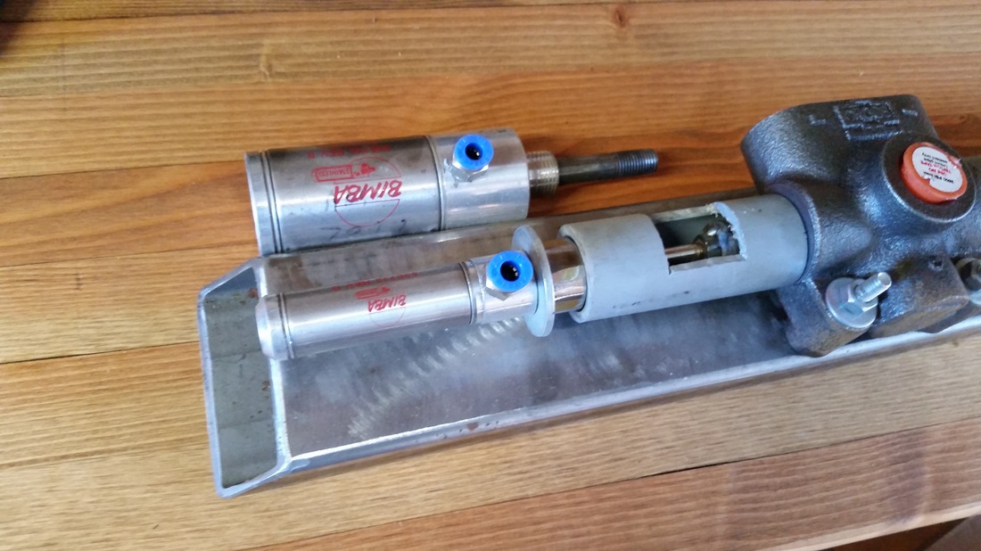
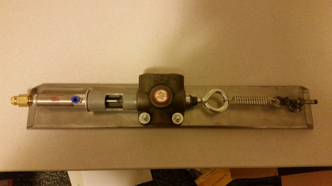
· The three components, cylinder/valve/spring will be mounted linearly on a base plate of 1”x3” tube.
· A PVC sleeve will be used to secure the cylinder in relation to the valve. This minimizes the possible side loading that could occur from hard mounting the cylinder in a misaligned state.
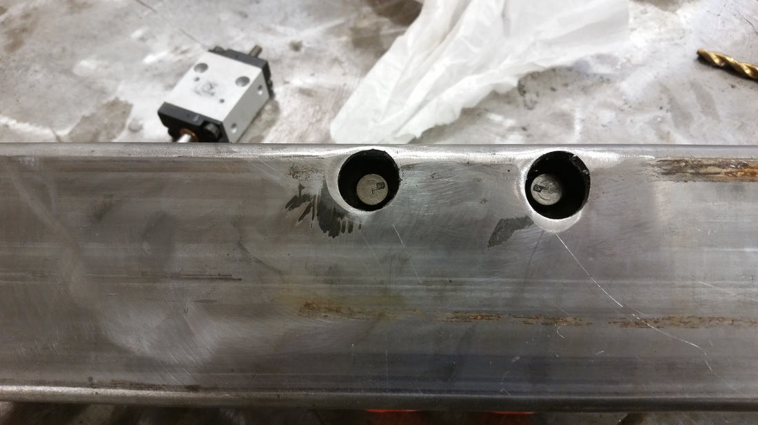
· Holes will be drilled in the base plate to match the ones in the valve. ¼” bolts will secure the valve to the base and will be countersunk so the base plate can be flush mounted.
· A ½” x 20 nut will be welded to the baseplate for tensioning bolt
· Tensioning bolt will have a hook welded on its head for the spring to attach.
· 3” Schedule 40 PVC pipe will be used due to its high pressure rating and thick walls that allow it to be easily drilled and tapped for pipe thread. Cast Iron could be used, but would be more expensive and harder to drill/tap. Copper is another possibility, but would be even more expensive and would require soldering threaded bungs in place. Schedule 40 PVC is rated at 240 psi and the system should never reach a pressure higher than 150.
· The column will have a 1” NPT port on the bottom that will plumed to the output of the emulsion pump using PVC flex line and barb fittings. There is already a 1” line on the emulsion tank that can be directly connected to the column.
· On the top of the column there will be a cap has 2 holes drilled and tapped to 1/4“ NPT. One will have a vacuum relief valve and the other a push fitting for the pneumatic pilot pressure.
· The column will be mounted at the top of the emulsion tank using zip ties to secure it to existing structure.
Adapting hydraulic valve
· One end of shaft will get a ¼-28 nut welded on it to accommodate the threads on the pneumatic cylinder shaft
· Opposing end of shaft will have a 3/8-16 nut welded on where an I-bolt will be inserted for connecting the tension spring.
Valve Bracket construction
· The three components, cylinder/valve/spring will be mounted linearly on a base plate of 1”x3” tube.
· A PVC sleeve will be used to secure the cylinder in relation to the valve. This minimizes the possible side loading that could occur from hard mounting the cylinder in a misaligned state.
· Holes will be drilled in the base plate to match the ones in the valve. ¼” bolts will secure the valve to the base and will be countersunk so the base plate can be flush mounted.
· A ½” x 20 nut will be welded to the baseplate for tensioning bolt
· Tensioning bolt will have a hook welded on its head for the spring to attach.
|
|
Testing
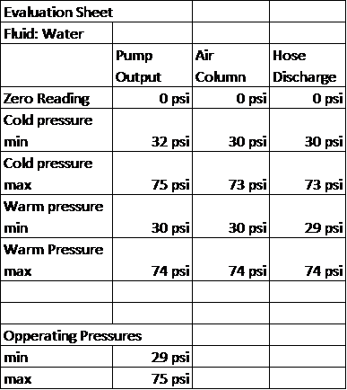
The pressure relief system was tested with water being pumped instead of emulsion. Water is a much cleaner and more consistent media to test the relief system. However, water is less viscous than the emulsion so overall pressure will be lower. A target of 40 psi minimum will be used for the water. Testing begins with pressure analysis. Pressure gauges are placed at the output of the Bowie pump, top of the air column, end of the transfer hose, and in the hydraulic motor circuit. These pressure gauge readings serve as a basis for optimization. Testing went as scheduled Longevity and performance testing will be performed in the summer of 2015.
First the emulsion tank is filled with 500 gallons of water. The gauge at the top of the column, output of the pump, and end of the hose are redundant for the static system, but should read different once fluid is flowing and dynamic pressure is being measured. Because water is a different viscosity the values will have to be adjusted. The precision of these pressure readings is good with the style pressure gauges I am using. Accuracy could be slightly off, but all the gauges were tested relative to each other to ensure accuracy. It is important to analyze the hydraulic system pressure when the fluid is cold and hot because the pressure relief system should operate steadily over these ranges.
The device will be tested as follows. Pressure readings will be taken as an average over a 30 second duration. Test will be conducted in my field.
1. With motor and pump off, take pressure readings from all 4 gauges to calibrate zero
2. Turn on hydraulic pump and take cold hydraulic pressure readings
3. Activate bowie pump with discharge open and record pressures
4. Shut discharge hose valve and record pressures
5. Tension spring to raise pressure or loosen it to lower pressure to reach target pressure
6. Repeat steps 2-6 until target pressure is reached
7. Repeat steps 2-6 for warm hydraulic fluid pressure readings
The test gave a maximum pressure of 75 psi and minimum pressure of 30 psi. The goal for the device was a minimum of 50 psi, which is easily within reach once emulsion is being pumped.
Results
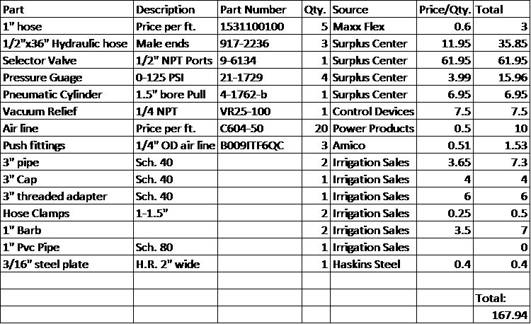
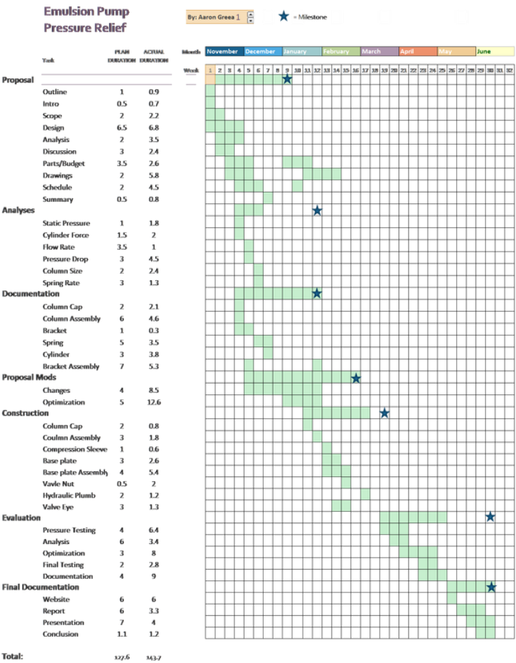
Budget
Schedule
Conclusion
The emulsion pressure relief device was a relative success because it did not allow the pressure to exceed the max for the system. When pumping water through the circuit the max pressure could be adjusted between 50-70 psi with a minimum pressure between 25-50 psi. During testing operations the column was able to keep the emulsion circuit and pneumatic circuit from cross contaminating. The pressure also remained steady across varying hydraulic fluid temperatures and consistencies.
The only criteria the device did not reach was being able to hold a consistent minimum pressure. This is due to an innate flaw in the hydraulic valve I use. There comes a state of hydraulic deadlock where the valve will bind in the middle. This leaves the emulsion pump at a pressure of 30-50 psi. After further investigation this same binding occurs in the flow control valve as well as the motor spool valve, preventing me from using the same cylinder/spring concept on one of those valves.
The only criteria the device did not reach was being able to hold a consistent minimum pressure. This is due to an innate flaw in the hydraulic valve I use. There comes a state of hydraulic deadlock where the valve will bind in the middle. This leaves the emulsion pump at a pressure of 30-50 psi. After further investigation this same binding occurs in the flow control valve as well as the motor spool valve, preventing me from using the same cylinder/spring concept on one of those valves.
